


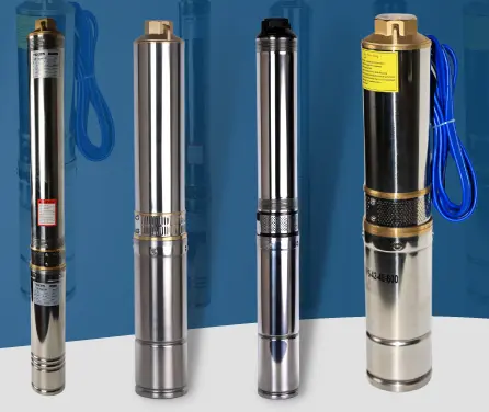
Installation steps and precautions for low-power deep well pumps
Pre-installation preparations
(I) Equipment and material inspection
- Pump Body inspection:
- Check whether the nameplate parameters (lift, flow, power) match the well depth and water demand (e.g., a pump with a lift of ≥60 meters should be selected for a well depth of 50 meters);
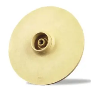
- Turn the impeller manually to confirm that there is no jamming or abnormal noise (the bearing should rotate smoothly without resistance).
- Accessory preparation:
- Required materials: wire rope (load bearing ≥ 2 times the weight of the pump), waterproof cable (national standard YHS type, cross-sectional area ≥1.5mm²), check valve (diameter consistent with the pump outlet), raw tape, sealant;
- Tools: pipe clamp, multimeter, megohmmeter (to measure insulation resistance), wellhead bracket (self-made or purchased cast iron bracket).
(II) Well body and environmental survey
- Well depth and water quality:
- Use a measuring rope to measure the well depth and ensure that the pump body dives ≥2 meters from the bottom of the well (to prevent sediment deposition from clogging the impeller);
- Test the sand content of the water quality (<0.01%). If the sand content is high, a pre-filter device needs to be installed.
- Power supply conditions:
- Single-phase pumps (220V) need to check the stability of the neutral and live voltages, and three-phase pumps (380V) need to confirm the three-phase balance (deviation ≤5%);
- Equipped with an independent distribution box and an overload protector (rated current is 1.2-1.5 times the rated current of the pump).
Detailed installation steps
(I) Pump body assembly and lowering into the well
- Connect the lifting parts:
- Install a lifting ring or wire rope fixing card on the upper end of the pump body, and the wire rope diameter should be ≥6mm (a 1.5kW pump weighs about 20kg, and the breaking tension of the wire rope should be ≥40kg);
- The cable is led out from the pump body junction box, and the joint is wrapped with 3 layers of waterproof tape, and then sealed with a heat shrink tube.
- Pump lowering operation:
- Slowly lower the pump body, and control the speed within 0.5 m/s to avoid collision with the well wall (sponge can be tied to the wire rope every 10 meters to buffer);
- After diving to the predetermined depth, fix the wire rope on the wellhead bracket to ensure that the pump body is suspended in the air and does not touch the bottom (≥1 meter from the water surface to prevent air inhalation).
(II) Pipeline system installation
- Water outlet connection:
- The pump outlet is connected to a hard PVC pipe (wall thickness ≥2mm) or a galvanized steel pipe, and the interface is wrapped with raw tape + sealant to prevent air leakage;
- Install pipe brackets every 3 meters to prevent the pipe from hanging in the air (especially the vertical pipe section).
- Check valve and control components:
- Install a check valve (facing upward) 1 meter away from the pump outlet to prevent the impeller from being damaged by water hammer when the pump is stopped;
- Install a ball valve or pressure switch at the end of the pipeline (for automatic control of pump start and stop, such as when used with a pressure tank).
(III) Electrical system connection
- Cable wiring:
- Single-phase pump: connect the live wire to the L terminal, the neutral wire to the N terminal, and the ground wire to the PE terminal (must be grounded, grounding resistance ≤4Ω);
- Three-phase pump: connect the U/V/W terminals according to the phase sequence. If the motor direction is reversed (small water output), any two live wires need to be swapped.
- Insulation test and protection:
- Use a megohmmeter to measure the insulation resistance of the motor winding (≥2MΩ). If it is lower than 0.5MΩ, it needs to be dried or repaired;
- Install a leakage protector in the distribution box (operating current ≤30mA, operating time ≤0.1 second).
Debugging and trial operation after installation
- First water filling and exhaust:
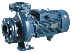
- Before starting, fill water from the end of the pipeline to exhaust the air in the pump body and pipeline (the Centrifugal Pump needs to be filled with water before starting);
- If it is a self-Priming Pump, inject an appropriate amount of clean water into the pump casing for the first use (according to the instructions).
- Trial operation inspection:
- After starting, observe whether the water flow rate meets the standard (such as the rated flow of a 1.5kW pump is 5m³/h, and the actual measurement should be ≥4.5m³/h);
- Detect the temperature of the motor casing (≤75℃) and listen for abnormal noise (normal operating noise ≤75dB);
- After running for 30 minutes, stop the machine to check whether the pipeline interface is leaking and whether the cable connector is hot.
Key points
(I) Safety and damage prevention points
- Anti-leakage protection:
- The pump body must be grounded (a 2.5-meter-long galvanized angle steel can be buried near the wellhead as a grounding electrode);
- The cable is prohibited from being entangled or heavily pressed, and the outdoor part must be protected by a PVC corrugated pipe.
- Anti-overload operation:
- It is prohibited to use it at a higher head (such as a pump with a rated head of 50 meters, the actual head is ≤45 meters);
- When the well water level drops to within 1 meter of the pump body, it is necessary to stop the pump to prevent idling (a water level float switch can be installed for linkage control).
(II) Environmental adaptability measures
- Low temperature protection:
- When installing in winter in northern regions, the pipeline needs to be wrapped with electric heating tape + insulation cotton (maintaining a temperature of ≥5℃);
- Before long-term shutdown, remove the drain bolt at the bottom of the pump body to drain the accumulated water to prevent freezing and cracking.
- Anti-corrosion treatment:
- When the water quality is acidic (pH < 6), choose a stainless steel pump body (304 material) and use PE pipe instead of a pipe;
- For installation in coastal areas, the motor junction box needs to be coated with waterproof sealant to avoid salt spray corrosion.
(III) Installation taboos and misunderstandings
- It is forbidden to use cables instead of wire ropes to lift the pump body (the cable's load-bearing capacity is insufficient, which may cause the pump body to fall);
- It is forbidden to force the pipe when installing (to avoid the pump body from bearing additional stress and causing bearing damage);
- After the three-phase pump is connected, it is necessary to test the steering direction first (reversal will cause a sharp drop in flow and damage the motor if it is running for a long time).
Installation optimization suggestions for different scenarios
Application scenarios Installation optimization points
- Household well water When paired with a pressure tank (50-100L), the pressure switch is set to an upper limit of 0.3MPa and a lower limit of 0.15MPa to achieve automatic start and stop;
- Agricultural irrigation A filter (50-mesh filter) is installed at the end of the pipeline to prevent mud and sand from entering the pump body; the pump body dives ≥3 meters from the bottom of the well;
- Commercial water supply Install a frequency converter (power ≥ 1.2 times the rated power of the pump) to automatically adjust the speed according to the water consumption to save energy and reduce consumption;
By standardizing the installation steps and controlling the details, the operating efficiency and service life of the low-power deep well pump can be ensured. If the well depth exceeds 80 meters or the water quality environment is complex, it is recommended to contact a professional installation team to avoid equipment damage or safety accidents due to improper operation.